We will start to craft our triangle now.
High Level Shading Language (HLSL)
We need to write some shaders using HLSL that control how our triangle will be rendered. In this example, a basic triangle only needs position and color.
For the GPU to understand what that even means, we have to create shaders:
- Vertex Shaders is where an operation happens on each vertex.
- Pixel Shaders is where an operation happens on each pixel to determine the appearance.
Our .hlsl code for the triangle will start out with 2 input structs. Similar to how C++'s int main() works, we will create similar functions for both the Vertex and Pixel shaders.
Note: We will combine the two shaders into single
.hlslfile. You can separate the two, but it is easier and readable in my opinion if all the information is on a single file for this example.
// @: Triangle.hlsl
struct VSInput {
    float3 position : POSITION;
    float4 color : COLOR;
};

struct PSInput {
    float4 position : SV_POSITION;
    float4 color : COLOR;
};
HLSL uses the float3 and float4 types. In C++, we have to create these with a custom class or an array, but in HLSL, it is a standard built in type.
The POSITION and COLOR are semantics. Simply, they are labels we defined that will later be utilized in our C++ code, so make sure to remember them! The semanics with the SV_ prefix are the System Value semantics, which have special meaning with the GPU.
In this example, the SV_POSITION states that the float4 position is the final clip space position of the vertex. The pipeline goes through multiple stages of transform matrix operations starting with our model space vertices that we will create from our triangle, but the end result will be in a float4 clip space hardware friendly format.
Now, let's look at the main for the Vertex Shader
// @: Triangle.hlsl
struct VSInput {
    float3 position : POSITION;
    float4 color : COLOR;
};

struct PSInput {
    float4 position : SV_POSITION;
    float4 color : COLOR;
};

PSInput VSMain(VSInput input) {
    PSInput output;
    output.position = float4(input.position, 1.0f);
    output.color = input.color;
    return output;
}
The float3 to float4 position might be of curiosity, but the GPU needs a 4D position value in clip space so it can determine what and what not to render out. The w component is used for perspective calculations, which is not used in this triangle example, but it is still needed.
Now, let's look at the pixel shader version of the main. Pay attention to the SV_TARGET semantic. The SV_TARGET system value semantic tells the GPU to write the float4 to the render target so we can see the final output on our monitors.
// @: Triangle.hlsl
struct VSInput {
    float3 position : POSITION;
    float4 color : COLOR;
};

struct PSInput {
    float4 position : SV_POSITION;
    float4 color : COLOR;
};

PSInput VSMain(VSInput input) {
    PSInput output;
    output.position = float4(input.position, 1.0f);
    output.color = input.color;
    return output;
}

float4 PSMain(PSInput input) : SV_TARGET {
    return input.color;
}
After the vertex shader processes finishes, a rasterizer pass runs for each of the SV_POSITION outputs to determine which pixels on screen are part of the triangle. It then interpolates the color across the geometry surface. When you get to the end of this post, you will see a gradient of colors for the triangle.
We simply just get those colors from the PSInput and tell the pixel shader to present to us those exact colors. We can override this with our own float4 color if needed, as well.
There is a lot of depth in .hlsl, after all, it is a whole entire language and we barely scratched the surface. But for our example, we have enough information to at least see how it behaves through the graphics pipeline.
DXC Compiler
As of writing this post, Shader Model 6.8 is the latest release from Microsoft. 10 years ago when Direct3D 12 launched, it started with Shader Model 5.1 only. We will stick with an older shader model 6_0 for compatibility reasons for older hardware.
Recent releases of the Shader Model had signifcant updates, such as support for Mesh Shaders, which can be more performant then the traditional input assembler pipeline.
With the released versions of Shader Model 6.x, Microsoft also released the DXC compiler. We will not be using the older FXC compiler in this post.
Many of the DXC related API exist in the <dxcapi.h> header. You can also use the dxc.exe that exists in newer version of windows to compile offline (compiling before we run our application). In this post though, we will work with the DXC compiler directly with its interface.
We will need these 3 objects from DXC.
// @: We will work in the Load() now!
void Load() override {
    Microsoft::WRL::ComPtr<IDxcUtils> dxcUtils;
    DxcCreateInstance(CLSID_DxcUtils, IID_PPV_ARGS(&dxcUtils));

    Microsoft::WRL::ComPtr<IDxcCompiler3> dxcCompiler;
    DxcCreateInstance(CLSID_DxcCompiler, IID_PPV_ARGS(&dxcCompiler));

    Microsoft::WRL::ComPtr<IDxcIncludeHandler> includeHandler;
    dxcUtils->CreateDefaultIncludeHandler(&includeHandler);
}
The end goal of using DXC is to get compiled bytecode code from our .hlsl code, which our computers read from. This is the job of the IDxcCompiler3.
Reading a .hlsl file
We're taking a small detour, because how do we exactly read our .hlsl? The C++ Standard Library has the <filesystem> so we will take advantage of that.
Your implementation might differ depending on where you want the organization of your code to look like, but in our case, the .hlsl file will live in the same folder as our .exe once we build.
Do keep in mind you need your build tool to copy over the .hlsl file into the build directory! If you are using the basic-window repo, just put it in the /shaders/ folder.
void Load() override {
    Microsoft::WRL::ComPtr<IDxcUtils> dxcUtils;
    DxcCreateInstance(CLSID_DxcUtils, IID_PPV_ARGS(&dxcUtils));

    Microsoft::WRL::ComPtr<IDxcCompiler3> dxcCompiler;
    DxcCreateInstance(CLSID_DxcCompiler, IID_PPV_ARGS(&dxcCompiler));

    Microsoft::WRL::ComPtr<IDxcIncludeHandler> includeHandler;
    dxcUtils->CreateDefaultIncludeHandler(&includeHandler);

    wchar_t exeBuf[MAX_PATH];
    GetModuleFileNameW(nullptr, exeBuf, MAX_PATH);
    std::filesystem::path exePath =
        std::filesystem::path(exeBuf).parent_path() / "triangle.hlsl";

    std::ifstream shaderFile(exePath, std::ios::binary);
    std::string shaderSource((std::istreambuf_iterator<char>(shaderFile)),
                              std::istreambuf_iterator<char>());

}
What we are doing here is taking the path of our .hlsl file and reading it with its raw bytes using std::ios::binary. The shaderSource will be the object that will be passed into the DXC api to be turned into a blob. In simple terms, a blob is a container for binary data.
Back to the DXC Compiler
But we still need an object that the DXC compiler takes in as a parameter. We create a IDxcBlobEncoding so the object handles the memory and lifetime. We then use a DxcBuffer, which is a simple struct that holds the blob's pointer and size. The DxcBuffer is the first parameter of the DXC compiler's method.
// @: Put it below the shaderSource code from earlier
void Load() override {
    //previous code omitted
    Microsoft::WRL::ComPtr<IDxcBlobEncoding> sourceBlob;
    dxcUtils->CreateBlob(shaderSource.data(), shaderSource.size(), CP_UTF8, &sourceBlob);

    DxcBuffer sourceBuffer;
    sourceBuffer.Ptr = sourceBlob->GetBufferPointer();
    sourceBuffer.Size = sourceBlob->GetBufferSize();
    sourceBuffer.Encoding = DXC_CP_UTF8;
}
Compiling the Shader Code
The next few steps will depend on how you wrote the .hlsl code. The file and function names will matter when we are compiling, so ensure the names in the .hlsl lines up with the .cpp code.
// @: LPCWSTR is a "Long Pointer to Constant Wide String"
void Load() override {
    //previous code omitted
    LPCWSTR vsArgs[] = {
      L"Triangle.hlsl",
      L"-E", L"VSMain",
      L"-T", L"vs_6_0",
      L"-Zi",
      L"-Od"
    };
}
The arguments list might seem a confusing as we are essentially treating the DXC CLI as an actual C++ function, but roughly:
- We are using the
Triangle.hlslas the file source name - with the
-Eentry point namedVSMain - with the
-Ttargetingvsvertex shader model6.0 - with the
-Zidebug info, and disabling optimizationO-d
When we compile, the function returns a IDxcResult, so we have to create that object, and then we can call the Compile() from our DXC compiler.
void Load() override {
    //previous code omitted
    LPCWSTR vsArgs[] = {
      L"triangle.hlsl",
      L"-E", L"VSMain",
      L"-T", L"vs_6_0",
      L"-Zi",
      L"-Od"
    };
    Microsoft::WRL::ComPtr<IDxcResult> vsResult;
    dxcCompiler->Compile(&sourceBuffer, vsArgs, _countof(vsArgs),
                         includeHandler.Get(), IID_PPV_ARGS(&vsResult));
}
Almost done compiling! We now need the IDxcBlob as that is the data container needed when we get to the Pipeline stage, so for now let us capture it.
void Load() override {
    //previous code omitted
    LPCWSTR vsArgs[] = {
      L"triangle.hlsl",
      L"-E", L"VSMain",
      L"-T", L"vs_6_0",
      L"-Zi",
      L"-Od"
    };
    Microsoft::WRL::ComPtr<IDxcResult> vsResult;
    dxcCompiler->Compile(&sourceBuffer, vsArgs, _countof(vsArgs),
                         includeHandler.Get(), IID_PPV_ARGS(&vsResult));
    Microsoft::WRL::ComPtr<IDxcBlob> vsBlob;
    vsResult->GetResult(&vsBlob);
}
Compiling is also very similar between the vertex shader and the pixel shader. You need to compile both.
I will leave it as an exercise to do the exact same process with the pixel shader. Most of it is refactoring any vs to ps.
Note: We are combining the vertex and pixel shader into a single file, but you can seperate the two if you would like.
Root Signature
The root signature can be thought of a .h file for the graphics pipeline. In other words, it is the function signature for a draw call. Let's first create one for our derived class.
class Basic : public App {
private:
    //previous members omitted
    Microsoft::WRL::ComPtr<ID3D12RootSignature> m_rootSignature;
}
Remember that our .cpp code is on the CPU, and the .hlsl is on the GPU. We define data in our .cpp files, such as a Sampler that is used for textures. To let the .hlsl code know about this Sampler, we have to put it in a slot. The root signature defines these slots and the type of data that goes into them. It is a contract between your .cpp and .hlsl code.
For our example, we are not using any constant buffers, samplers, or anything where the root signature has a role. But since we are now going through the full graphics pipeline with our triangle, we still need a root signature. Therefore, we will create an empty root signature to use.
There are multiple ways to create a root signature. Either in .cpp or .hlsl. For this example, we will create the root signature inside our Triangle.hlsl.
Root signatures using HLSL are well documented if you seek more information.
We just have to define the root signature with a define.
// @: Put at the very top of the Triangle.hlsl
#define RootSig \
    "RootFlags(ALLOW_INPUT_ASSEMBLER_INPUT_LAYOUT)"
This workflow is nice because we can define our pipeline's "function signature" right next to the code that uses it. By using the [RootSignature(RootSig)] attribute, we tell the DXC compiler to bake our Root Signature definition directly into the shader bytecode.
The ALLOW_INPUT_ASSEMBLER_INPUT_LAYOUT flag is important here. It tells the hardware that this pipeline expects vertex data to be fed in via the Input Assembler (our vertex buffer) rather than being fetched manually in the shader.
// @: Place above the VSMain in the Triangle.hlsl
[RootSignature(RootSig)] //Above the VSMain!
PSInput VSMain(VSInput input) {
    PSInput output;
    output.position = float4(input.position, 1.0f);
    output.color = input.color;
    return output;
}
Now, it is trivial to get the root signature directly from our shader code. We create another IDxcBlob and use the same vsResult we had earlier to get the root signature.
void Load() override {
    //previous code omitted
    Microsoft::WRL::ComPtr<IDxcBlob> rootSigBlob;
    vsResult->GetOutput(DXC_OUT_ROOT_SIGNATURE,
                        IID_PPV_ARGS(&rootSigBlob), nullptr);
    m_device->CreateRootSignature(0, rootSigBlob->GetBufferPointer(),
                                  rootSigBlob->GetBufferSize(),
                                  IID_PPV_ARGS(&m_rootSignature));
}
Since the rootSigBlob has our data, we just get our ID3D12Device to call CreateRootSignature.
Again, we are declaring how the data flows in from the .hlsl we write. In other words, the root signature exposes resources to the shaders.
Pipeline State Stream
The pipeline state is where we bring in all the different options and settings we want for a draw call into a large structure to be used by the graphics driver.
As always, let us create the member.
class Basic : public App {
private:
    //previous members omitted
    Microsoft::WRL::ComPtr<ID3D12RootSignature> m_rootSignature;
    Microsoft::WRL::ComPtr<ID3D12PipelineState> m_pipelineState;
}
Objects that we already made, such as the root signature and shaders, will be used as parameters. Other settings like topology, and input layout will also be part of the pipeline.
Topology is how we want to render our geometry, should it be triangles? or just lines?
Input Layout is the struct that we defined earlier in our .hlsl, which is where our semantic names are now coming in handy. We have to tell the pipeline how our vertex data is composed. Put this code after where we created the root signature.
void Load() override {
    D3D12_INPUT_ELEMENT_DESC inputElementDescs[] = {
    {"POSITION", 0, DXGI_FORMAT_R32G32B32_FLOAT, 0, 0,
     D3D12_INPUT_CLASSIFICATION_PER_VERTEX_DATA, 0},
    {"COLOR", 0, DXGI_FORMAT_R32G32B32A32_FLOAT, 0, 12,
     D3D12_INPUT_CLASSIFICATION_PER_VERTEX_DATA, 0}};
 }
There are many more settings that we will not get to for our small example, such as blends and stencils. Pipelines are convenient as you can just tell the command list to switch to another created pipeline. For example, if you have a pipeline dedicated to drawing lines only as part of a debug build, then you can easily switch which pipeline you want to use at a given time.
Traditionally, we created D3D12_GRAPHICS_PIPELINE_STATE_DESC, but updates later on supported the use of D3D12_PIPELINE_STATE_STREAM_DESC, which is what we will use.
Initially, the pipeline state stream is a lot less verbose for our triangle example, so let us create it. We have to define the struct ourselves using the d3dx12.h helpers.
// @: Don't forget the Input Layout from above!
void Load() override {
    //previous code omitted
    struct PipelineStreamStruct
    {
        CD3DX12_PIPELINE_STATE_STREAM_ROOT_SIGNATURE pRootSignature;
        CD3DX12_PIPELINE_STATE_STREAM_INPUT_LAYOUT InputLayout;
        CD3DX12_PIPELINE_STATE_STREAM_PRIMITIVE_TOPOLOGY PrimitiveTopologyType;
        CD3DX12_PIPELINE_STATE_STREAM_VS VS;
        CD3DX12_PIPELINE_STATE_STREAM_PS PS;
        CD3DX12_PIPELINE_STATE_STREAM_RENDER_TARGET_FORMATS RTVFormats;
    };
}
We can add more to this struct later on if needed, but for our use case, this is the bare minimum.
We need to fill in the PipelineStreamStruct that we made. Good thing we already have most of the parameters made, and it is just a matter of grabbing those pointers.
// @: Don't forget the Input Layout from above!
void Load() override {
    //previous code omitted
    struct PipelineStreamStruct
    {
        CD3DX12_PIPELINE_STATE_STREAM_ROOT_SIGNATURE pRootSignature;
        CD3DX12_PIPELINE_STATE_STREAM_INPUT_LAYOUT InputLayout;
        CD3DX12_PIPELINE_STATE_STREAM_PRIMITIVE_TOPOLOGY PrimitiveTopologyType;
        CD3DX12_PIPELINE_STATE_STREAM_VS VS;
        CD3DX12_PIPELINE_STATE_STREAM_PS PS;
        CD3DX12_PIPELINE_STATE_STREAM_RENDER_TARGET_FORMATS RTVFormats;
    };
    PipelineStreamStruct psoStream = {};
    psoStream.pRootSignature = m_rootSignature.Get();
    psoStream.InputLayout = {inputElementDescs, _countof(inputElementDescs)};
    psoStream.PrimitiveTopologyType = D3D12_PRIMITIVE_TOPOLOGY_TYPE_TRIANGLE;
    psoStream.VS = CD3DX12_SHADER_BYTECODE(vsBlob->GetBufferPointer(), vsBlob->GetBufferSize());
    psoStream.PS = CD3DX12_SHADER_BYTECODE(psBlob->GetBufferPointer(), psBlob->GetBufferSize());
    psoStream.RTVFormats = {.RTFormats = {DXGI_FORMAT_R8G8B8A8_UNORM}, .NumRenderTargets = 1};
}
Since we used the d3dx12.h helpers but we need a D3D12_PIPELINE_STATE_STREAM_DESC, we simply just give the desc our psoStream. Finally, just like our root signature, we ask the ID3D12Device to CreatePipelineState.
// @: Right after the previous code
void Load() override {
    //previous code omitted
    D3D12_PIPELINE_STATE_STREAM_DESC streamDesc = {sizeof(psoStream), &psoStream};
    m_device->CreatePipelineState(&streamDesc, IID_PPV_ARGS(&m_pipelineState));
}
The pipeline is now complete, but we never discussed what a viewport is and how and where the geometry should be rendered.
Viewport and Scissor
Viewport
We need to define what our view will look like. In most cases, it will just be the entirety of the window.
After the graphics goes through all the stages, geometry will be rendered in normalized device coordinates (NDC), where the X and Y will range from -1 to 1.
class Basic : public App {
private:
    //previous members omitted
    D3D12_VIEWPORT m_viewport;
}
The D3D12_VIEWPORT has to conform to the NDC ranges after the pipeline, so we define our struct in pixel space first, meaning that 0,0 will be the top left corner of our monitor, and using the Width and Height parameters for our screen.
// @: Put after the pipeline code.
void Load() override {
    //previous code omitted
    m_viewport.TopLeftX = 0.0f;
    m_viewport.TopLeftY = 0.0f;
    m_viewport.Width = static_cast<float>(GetWidth());
    m_viewport.Height = static_cast<float>(GetHeight());
    m_viewport.MinDepth = 0.0f;
    m_viewport.MaxDepth = 1.0f;
}
Scissor
But what happens if we zoom really far into our triangle where parts of it are now off screen not in the viewport? For that, we need a D3D12_RECT to define our scissor in order to cull pixels that are outside this rectangle. If we are not going to see it, do not bother rendering it.
class Basic : public App {
private:
    //previous members omitted
    D3D12_VIEWPORT m_viewport;
    D3D12_RECT m_scissorRect;
}
Parameters will be similar. Note the D3D12_RECT uses long instead of float.
void Load() override {
    //previous code omitted
    m_viewport.TopLeftX = 0.0f;
    m_viewport.TopLeftY = 0.0f;
    m_viewport.Width = static_cast<float>(GetWidth());
    m_viewport.Height = static_cast<float>(GetHeight());
    m_viewport.MinDepth = 0.0f;
    m_viewport.MaxDepth = 1.0f;
    m_scissorRect.left = 0;
    m_scissorRect.top = 0;
    m_scissorRect.right = static_cast<LONG>(GetWidth());
    m_scissorRect.bottom = static_cast<LONG>(GetHeight());
}
Triangle Geometry
We are now ready to tell the GPU about our triangle that we will create by hand. This will perhaps be the most complicated part of this post as we are now dealing with buffers, descriptors, heaps, and mapping. We will take it one step at a time though.
Creating the Vertex
As discussed in the .hlsl section, our triangle only needs a position and color.
Note: We are using the
<DirectXMath.h>library that comes with the Windows SDK, but any math library will work. For our triangle, a math library might even be overkill.
class Basic : public App {
private:
    //previous members omitted
    struct Vertex {
        DirectX::XMFLOAT3 position;
        DirectX::XMFLOAT4 color;
    };

}
Recall the NDC system and envision how and where our triangle vertices should be. We need one vertex somewhere near the top middle, and the bottom 2 vertices can be to the left and right.
// @: Put under the viewport code
void Load() override {
    //previous code omitted
    using namespace DirectX;
    Vertex triangleVertices[] = {
        // Top - Red
        {XMFLOAT3(0.0f, 0.5f, 0.0f),
        XMFLOAT4(1.0f, 0.0f, 0.0f, 1.0f)},
        // Bottom right - Green
        {XMFLOAT3(0.5f, -0.5f, 0.0f),
        XMFLOAT4(0.0f, 1.0f, 0.0f, 1.0f)},
        // Bottom left - Blue
        {XMFLOAT3(-0.5f, -0.5f, 0.0f),
        XMFLOAT4(0.0f, 0.0f, 1.0f, 1.0f)}};
    };
}
The Heap
We have geometry now, but our GPU has no way of knowing about it. So, let's ask the GPU to dedicate some of memory for our triangle. For many of the structs we create, we have to track the size of the datas we eventually want to bring over to the GPU.
// @: Put under the triangleVertices code
void Load() override {
    //previous code omitted
    const UINT vertexBufferSize = sizeof(triangleVertices);
}
The heap memory in the GPU works best when it is doing GPU related tasks, but we have to sometimes get our data that lives in our CPU, as the case for our vertices, into the GPU memory.
Therefore, Direct3D provides the enum D3D12_HEAP_TYPE. You can read more if curious, but we will work with the D3D12_HEAP_TYPE_UPLOAD which allows us CPU access to the GPU memory for uploading data. We are using the <d3dx12.h> helper to give us defaults for the inherited D3D12_HEAP_PROPERTIES struct.
The CD3DX12_RESOURCE_DESC is a <d3dx12.h> helper as well that inherits D3D12_RESOURCE_DESC that gives a default descriptor. We went over the purpose of descriptors before, but again they are struct that tells the GPU how to interpret this data. The helper tells the GPU it is a buffer with the size vertexBufferSize.
void Load() override {
    //previous code omitted
    const UINT vertexBufferSize = sizeof(triangleVertices);
    auto heapProps = CD3DX12_HEAP_PROPERTIES(D3D12_HEAP_TYPE_UPLOAD);
    auto bufferDesc = CD3DX12_RESOURCE_DESC::Buffer(vertexBufferSize);
}
Committing the Resource
We described how our vertices how it should live in memory, but we have not told the GPU to actually allocate memory. Let's create a ID3D12Resource like we did previously for our vertex buffer. Reminder that a resource is quite generic, which is why we need the descriptors to help the GPU know what the data is.
class Basic : public App {
private:
    // previous code omitted
    Microsoft::WRL::ComPtr<ID3D12Resource> m_vertexBuffer;
}
Committing a resource will get the GPU to allocate the heap needed for our vertices to live in. It is a single function call from our ID3D12Device.
void Load() override {
    //previous code omitted
    const UINT vertexBufferSize = sizeof(triangleVertices);
    auto heapProps = CD3DX12_HEAP_PROPERTIES(D3D12_HEAP_TYPE_UPLOAD);
    auto bufferDesc = CD3DX12_RESOURCE_DESC::Buffer(vertexBufferSize);

    m_device->CreateCommittedResource(
        &heapProps, D3D12_HEAP_FLAG_NONE,
        &bufferDesc, D3D12_RESOURCE_STATE_GENERIC_READ,
        nullptr, IID_PPV_ARGS(&m_vertexBuffer));
}
We created many of these paramters already, but note the D3D12_RESOURCE_STATE_GENERIC_READ which is the method call paramter for InitialResourceState. When the GPU is created, we want it to be in certain states. We are uploading our data for the GPU to read from, so we set it as such.
Sending to the GPU
So far, we have created some buffer that is completely empty on the GPU. Sure, it knows it has a size of vertexBufferSize and that it can be read from, but it has nothing in it. Therefore, we have to map and memcpy our CPU data for the GPU. Let's start out by creating the UINT8* pointer and CD3DX12_RANGE.
void Load() override {
    //previous code omitted
    UINT8* pVertexDataBegin;
    CD3DX12_RANGE readRange(0, 0);
}
We need the pointer as we are working with bytes. After our operations in this section, this pointer will reference the GPU buffer's memory.
The CD3DX12_RANGE tells the GPU how much of the memory the CPU might read. We are just writing our buffer to the GPU and we don't need to read anything, so we just create an empty CD3DX12_RANGE. This be non-empty if in the future you want to create directly from the GPU.
The next snippets of code allows us access the GPU memory with the UINT* we created before.
void Load() override {
    //previous code omitted
    UINT8* pVertexDataBegin;
    CD3DX12_RANGE readRange(0, 0);

    m_vertexBuffer->Map(0, &readRange,
        reinterpret_cast<void**>(&pVertexDataBegin));
    memcpy(pVertexDataBegin,
           triangleVertices,
           sizeof(triangleVertices));
    m_vertexBuffer->Unmap(0, nullptr);
}
We are calling the ID3D12Resource's method that currently is somewhere in the GPU memory and Map it to where it begins to our UINT8*.
With our pointer, we can now bring our actual triangleVertices array into the GPU with the memcpy call. This function call is from the C/C++ standard library that just copies over a certain amount of bytes over to some pointer. In other words, we are copying the bytes from the triangle array into the UINT8*, which is where the GPU memory is referenced.
When you are done working with the GPU memory, you have to Unmap it. This tells the GPU driver that we are done doing what we had to do, and the GPU can continue working.
The Vertex Buffer View
The GPU officially has our vertex array into the GPU memory in the form of bytes. We know it is a triangle, but the GPU does not. This is where we define the view so the GPU can interpret our uploaded data correctly and render our triangle.
Let's start by creating the view member in our class. Luckily for us, the struct is aptly named.
// @: Right below the m_vertexBuffer we created earlier
class Basic : public App {
private:
	Microsoft::WRL::ComPtr<ID3D12Resource> m_vertexBuffer;
	D3D12_VERTEX_BUFFER_VIEW m_vertexBufferView;
}
We just need to fill in the variables for D3D12_VERTEX_BUFFER_VIEW.
void Load() override {
    //previous code omitted
    m_vertexBufferView.BufferLocation = m_vertexBuffer->GetGPUVirtualAddress();
    m_vertexBufferView.StrideInBytes = sizeof(Vertex);
    m_vertexBufferView.SizeInBytes = vertexBufferSize;
}
BufferLocationis the memory address of the buffer that lives on the GPU side. It tells the GPU where the start of our data is.StrideInBytestells the GPU how far to advance the bytes when reading. Again, we are working with bytes. Ourm_vertexBuffercontains the array ofVertex, and we want to read each one of those.SizeInByteswill be filled in from our earliervertexBufferSizevariable we created.
Our triangle data now lives in the GPU. Of course, that doesn't mean it knows how to render it. That will be in our Update() function where we tell the command list how to interpret our geometry.
To recap this section, we have the m_vertexBuffer which holds the pure data, and the m_vertexBufferView that tells the GPU what our data is.
Updating our Command List
Almost there, we now have to update our Update().
Recall in our per-frame function, all our drawing is done only after we transition to the D3D12_RESOURCE_STATE_RENDER_TARGET.
The command list has many methods with prefixes that you will see throughout the codebase. One of those is OM, which is the Output Merger that exists in the final stages of the graphics pipeline. This is where the pixel shader contents are blended into the final texture, our render target.
As such, we are setting our canvas for all the following drawing commands. We will call the OMSetRenderTarget with our rtvHandle we created earlier to let the command list where our render target is located.
Note: We are not working with depth stencils, so we put
nullptrfor the last parameter inOMSetRenderTarget.
void Update() override {
    // previous code omitted...
    CD3DX12_CPU_DESCRIPTOR_HANDLE rtvHandle(m_rtvHeap->GetCPUDescriptorHandleForHeapStart(),
                                            m_frameIndex, m_rtvDescriptorSize);

    m_commandList->OMSetRenderTargets(1, &rtvHandle, FALSE, nullptr);

    const float clearColor[] = {0.33f, 0.33f, 0.33f, 1.0f};
    //rest of the code we wrote already...
}
We did a lot of work with the root signature, pipeline, and viewports, so now its a matter of telling the command list that it exist and it should use it.
void Update() override {
    // previous code omitted ...
    m_commandList->ClearRenderTargetView(rtvHandle, clearColor, 0, nullptr);

    m_commandList->SetGraphicsRootSignature(m_rootSignature.Get());
    m_commandList->SetPipelineState(m_pipelineState.Get());
    m_commandList->RSSetViewports(1, &m_viewport);
    m_commandList->RSSetScissorRects(1, &m_scissorRect);
    //rest of the code we wrote already...
}
Finally, our draw commands will be done in 3 steps. We are now working with the IA, which is the Input Assembler. This is the stage where the raw vertex data we created will now be made into actual geometry.
We must let the pipeline know that we intend this geometry to be a D3D_PRIMITIVE_TOPOLOGY_TRIANGLELIST, which means "form a triangle using the next 3 vertices from my uploaded array in the buffer". There are many kinds of topologies available, but we are only working with triangle lists.
The rest of the commands are just a matter of setting the buffer and drawing them.
void Update() override {
    // previous code omitted ...
    m_commandList->ClearRenderTargetView(rtvHandle, clearColor, 0, nullptr);

    m_commandList->SetGraphicsRootSignature(m_rootSignature.Get());
    m_commandList->SetPipelineState(m_pipelineState.Get());
    m_commandList->RSSetViewports(1, &m_viewport);
    m_commandList->RSSetScissorRects(1, &m_scissorRect);

    m_commandList->IASetPrimitiveTopology(D3D_PRIMITIVE_TOPOLOGY_TRIANGLELIST);
    m_commandList->IASetVertexBuffers(0, 1, &m_vertexBufferView);
    m_commandList->DrawInstanced(3, 1, 0, 0);
    //rest of the code we wrote already...
}
IASetPrimitiveTopologythe vertex buffer view that we created earlier. We are using the0slot that we defined earlier in theD3D12_INPUT_ELEMENT_DESC. Then we are setting1view.DrawInstancedwith3vertices that make our triangle. We only need1instance (count), which starts at vertex location0and0instance location. The last paramter is only for instancing.
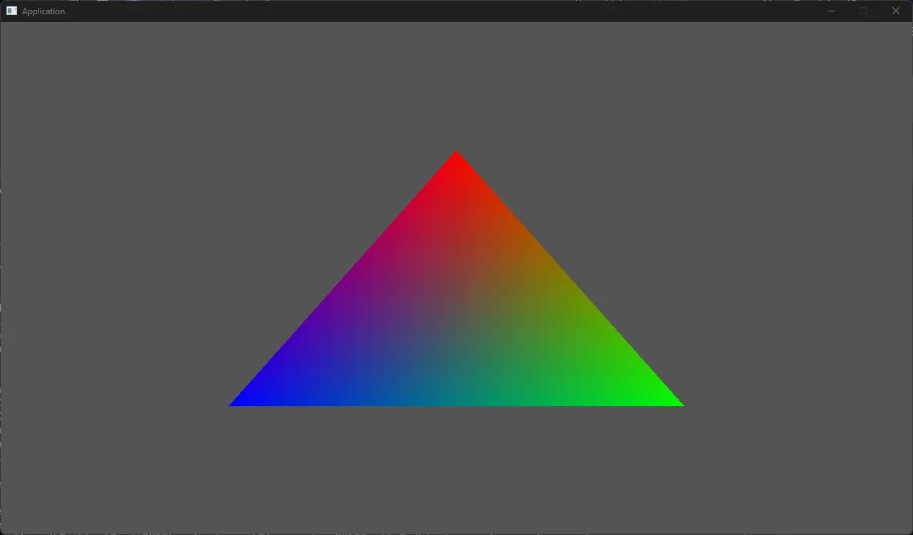
Conclusion
We now have a triangle! But some disclaimers, we skipped many error checking and debugging enabling that is crucial to graphics programming. As an exercise, adding safety checks to gracefully handle errors, and output helpful messages when crashing is extremely helpful.
Throughout the use of the Direct3D API, you will find yourself rewriting many of patterns, so it is best to create your own helpers to make life a bit easier. A good first helper to create is a buffer class that has methods for uploading, perhaps in a single call instead of our multiple lines of code we did.